

Vision measurement systems for precision optical measurement.
A vision measurement system captures an image of a component and measures its geometry from that image — edges, diameters, distances and radii — instead of touching it with a probe or gauge.
This page explains what is inside such a system, what decides its performance and how to choose one. The machines that put it to work are the Visimaster Visigauge range.
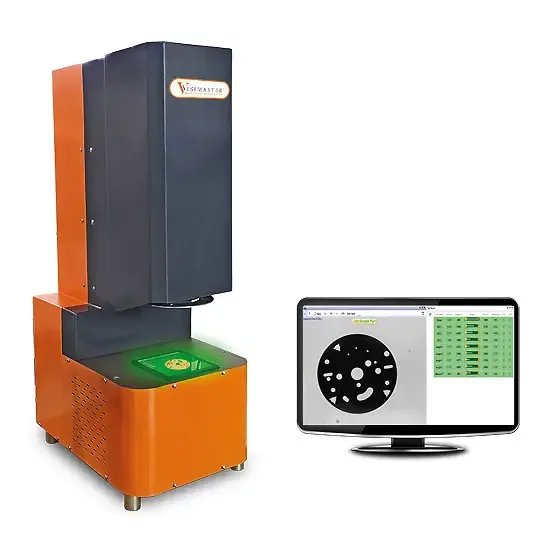
What a vision measurement system is made of
- Industrial camera — captures the component image; chosen for the part size, field of view and required resolution
- Precision optics — project the part onto the sensor as a stable silhouette the software can measure
- Controlled illumination — backlighting or engineered lighting creates clean edges and suppresses reflections and shadows
- Image processing — edge detection and feature extraction turn pixels into geometric features
- Measurement software — computes dimensions, evaluates tolerances, stores measurement programs and produces batch and SPC records
From part to report in seven steps
- 1
Part positioning
The component is presented to the optical system in a repeatable fixture.
- 2
Illumination
Lighting creates contrast between the part and its background.
- 3
Image acquisition
The camera captures the part through the precision optics.
- 4
Image processing
Software identifies the edges and geometric features that matter.
- 5
Measurement
Algorithms compute every programmed dimension from those features.
- 6
Tolerance evaluation
Each result is compared with the drawing specification.
- 7
Data recording
Results are stored for batch reports, SPC and traceability.
What decides measurement performance
The camera alone does not fix the accuracy. These factors do, together:
- Component size and geometry
- Required tolerance
- Camera resolution
- Lens and field of view
- Lighting conditions
- Part positioning and fixture
- Surface finish and reflectivity
- Calibration quality
- Mechanical stability
- Measurement algorithms
- Operating environment
How to select the right vision measurement system
Bring these to the feasibility discussion and the configuration follows:
- Component — size, geometry and material
- Dimensions — the features and parameters to be measured
- Tolerance — the measurement capability required
- Volume — parts per shift, so the inspection rate is right
- Surface — finish, reflectivity and contrast
- Data — reporting, SPC and traceability requirements
- Integration — existing machines and production systems
One instrument, many names
Visimaster designs and builds these vision measurement systems itself, at its Bhosari works in Pune. A vision based measurement system from a single maker is simpler to live with: one team answers for the camera, the fixture, the software and the report.
Among vision measurement systems manufacturers in India, the same instrument is sold under several names — vision measuring system, visual measurement system, one click measurement system, video measuring machine — and they all describe the same principle: a camera measures the part from its image, and nothing touches the part.
Video measuring machine for rubber and plastic parts
A video measuring machine for rubber parts or small plastic parts has one job a contact gauge cannot do: measure without pressing on the part. Rubber components, small plastic parts, pressed and stamped parts lie flat on the Vertical Visigauge stage, the camera images them from above and every programmed dimension is read from the image.
Turned and shaft-type parts are the Horizontal Visigauge's work instead. Bring samples of both kinds to the feasibility study and the engineer places each family on the right machine.
Visimaster vision measurement systems
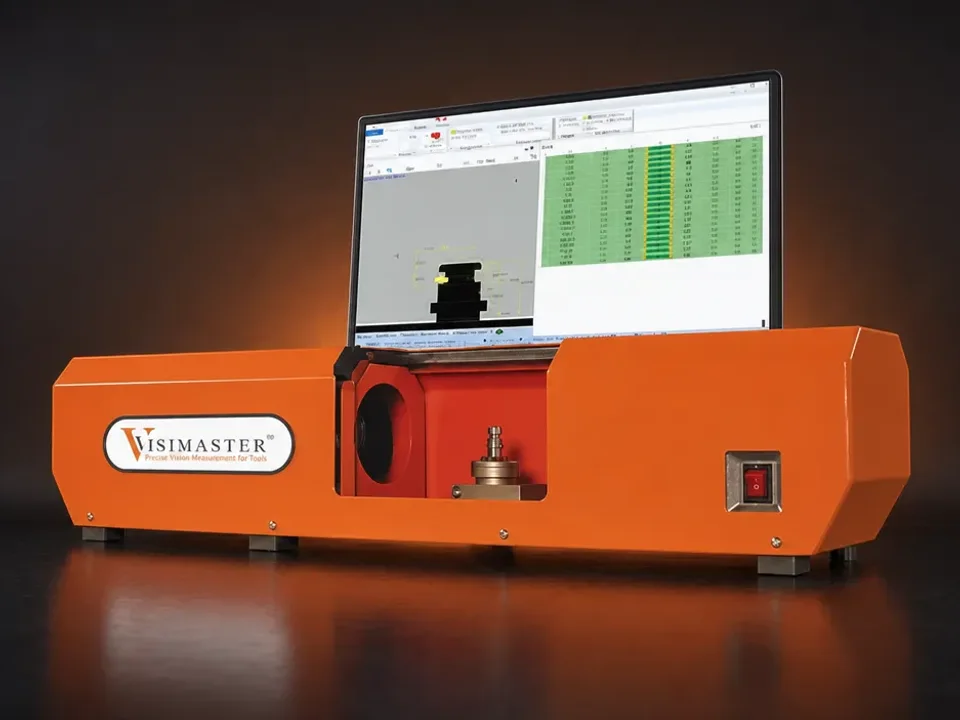
Horizontal Visigauge
One-click gauging of 25+ dimensions in a fraction of a second — the horizontal type, for turned, automotive and precision machined parts.
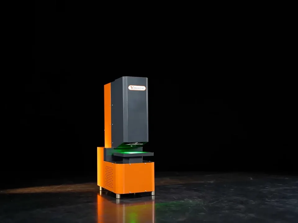
Vertical Visigauge
One-click gauging of 25+ dimensions in a fraction of a second — the vertical type, for pressed, stamped, rubber and precision machined parts.
Where vision measurement is used
- Automotive components
- Precision engineering and turned parts
- Fasteners
- Brass and metal components
- Plastic and rubber components
- Stamped components
- Electronics
The Horizontal Visigauge and what its operator sees
The machine, sample parts and the measurement result screens from our own catalogue.
Both Visigauge orientations measuring
From our own YouTube channel — press play to load a film.
Horizontal Visigauge: high-speed vision measuring for precision parts
Precision measurement with the Vertical Visigauge
Questions buyers ask
Which Visigauge orientation do I need?
Side view (Horizontal) for turned and shaft-type parts and threads; top view (Vertical) for flat, pressed and profile parts. Send a drawing or samples and the engineer confirms the orientation and field of view.
What is the difference between a vision measurement system and a vision measuring machine?
The system is the camera, optics, lighting and software. The machine adds the stage, fixture, enclosure and operator workflow — the Visigauge is a complete machine built around such a system.
When is vision measurement the right choice?
When you need several dimensions at once, non-contact inspection, repeatable results, digital records with SPC and batch reports, or faster inspection than manual gauging allows.
Is a stated micron value enough to choose a system?
No. Repeatability is a property of the whole application — part, fixture, optics, lighting and calibration. Evaluate with the actual component, drawing and tolerances.
Which parts benefit most from non-contact measurement?
Delicate components, small precision parts, parts that deform under a probe, and any high-volume dimensional inspection where consistency matters.
Which measuring machine fits your part?
Send a drawing with the dimensions and tolerances you need, or courier sample parts to our Bhosari lab. A vision engineer confirms the field of view, the repeatability model and the fixture — free.
Contact the works